Saturday, December 29, 2012

Practical experiences with Go Pro Hero 2


Edited results you can expect: http://youtu.be/u4ztyGLMCjg

Everything worked as expected except for the fogging.

It fogs. It fogs because moisture on the inside of the camera waterproof enclosure (and from within the camera) condenses on the inside surface of the waterproof enclosure. What was particularly annoying was that the surface on which moisture first condensed was the colder surface, which happens to be the thinner lens cover.

Fogging was partially abated by putting car A/C on max and recirculate and having the vent directed into a bag containing the Go Pro. After the A/C sufficiently dehumidified and cooled things, the Go Pro was assembled and then brought outside.

Why does it fog? The outside is colder than the inside. But what makes the fogging problem complex is that the inside will not equalize with the outside because running the camera generates heat. In very cold climates, this heat is welcome since it keeps the camera circuitry warm. In not so cold climates, then it is not so welcome. So, dealing with this problem is about striking a balance running the camera.

Fog thoughts/observations:

The conditions were Hawaiian coastal water temps in November about 79F/26C. The air was a little bit warmer. The interior of the camera must have been quite warm.

Once condensation occurs, more condensation continues to occur in the exact same place. Is this due to the surface accumulating dirt? A place where condensation would preferentially gather other than the inside surface of the lens would be super useful. Maybe the enclosure can be modified for such a behavior.

'Set and forget' simply didn't work at all. The camera would run, heat and then fog. I believe the faster/higher resolution modes make the camera hotter. I also believe that a newer, more highly charged battery generates more heat as it initially discharges.

'Record on launch' where the camera is left on but only put into recording mode for a wave worked fairly well, but the recording and stopping had to be done at the beginning and ending of a ride otherwise condensation would accumulate.

The moment condensation is observed, powering the camera down and letting it cool was the best strategy.

The best no fog strategy was to paddle out with the camera off, turn it on for a set and record before launch. After paddling out of the inside as all courteous surfers should immediately do, repeating turning off the camera for the paddle out was the trick.

This camera cycling strategy was best served by keeping the nose of the board along with the camera underwater while waiting in the lineup for the next ride.

Would anti-fog in the inside of the lens work?

Remaining thoughts/observations:

The camera needs a quick trash that throws out the last recording or picture. Maybe it does this. But what would be great is a button sequence to power down and save or to power down and delete.

Didn't explore the sequential picture modes but think that they will be just as challenging with fog due to the 'set and forget' heat issues.

There was little regret in spending the money on the largest SD card possible. Lots of data gets generated.

The USB charging is perilous if a laptop computer sleeps and powers down the USB port causing the camera to not charge.

Be prepared to learn more than you probably want on dealing with video files and the technical issues associated with them.

Older locals don't like these things. One bit. And the aggro local treatment kooks receive is pretty quick and much more severe. It was amazing to see the reactions. Locals were divided into two categories: One of fury and hate and the other of intellectual curiosity. The non-locals and kooks were less stimulated and more or less wanted to know if it worked well. It felt like wearing a huge billboard that advertises bad things for the user. So don't go out without knowing how to operate the camera with your eyes closed. Practice and learn to stop/start the camera in a second or two while mounted on your board. Don't dismount the board to operate it. Being a kook with it is one thing, being dangerous fumbling with it on the inside or on launch is quite another.
Wednesday, April 8, 2009

divs and tables...

There are a myriad of resources on the net that treat the topic of divs and tables. So look further if you are interested in the pros and cons or browser compatibility issues to name a few.

I've had two recent encounters regarding the topic of divs and tables. One was about the matter of which was better, divs or tables, and the other about a more esoteric need to have a grid of UI widgets that both horizontally and vertically move in a proportional way to the browser window.

So I figured to do a little catch up and one of the notable things encountered was that there are incredibly useful examples on the net. The second observation I had was that it was next to impossible to avoid the temptation of throwing in some Javascript for the exact behavior that I wanted. But being more interested in wondering what basic xhtml could do in conjunction with CSS led me to need basic or naive examples for experimentation.

So here are two tables I managed to get working that might serve use as input for more detailed examination of what is going on with the markup, styles and browsers. There are some interesting places to go.

Please don't complain about MSIE not working with this. :-)


<?xml version="1.0" encoding="iso-8859-1"?>
<!DOCTYPE html PUBLIC "-//W3C//DTD XHTML 1.1//EN" "xhtml11.dtd">
<html xmlns="http://www.w3.org/1999/xhtml" xml:lang="en">
<head>
<style>
html, body
{
margin: 0px;
padding: 0px;
height: 100%;
}

/* global */
.a
{
background-color:#7F7049;
}
.b
{
background-color:#CCA338;
}
.cellContent
{
text-align: center;
background-color:#A9D6B9;
}

/* first table */
.cell1
{
float: left;
width: 25%;
height:25%;
}


/* second table */
.table2
{
width:100%;
display: table
}
.row2
{
display: table-row;
}
.cell2
{
display:table-cell;
padding: 10px;
}

</style>

</head>
<body>
<p>Table using float and clear properties; demonstrates vertical browser resize.</p>
<div class="cell1 a">
<div class="cellContent">CellContent</div>
</div>
<div class="cell1 b">
<div class="cellContent">CellContent</div>
</div>
<div class="cell1 a">
<div class="cellContent">CellContent</div>
</div>
<div class="cell1 b">
<div class="cellContent">CellContent</div>
</div>
<br style="clear:both;"/>
<div class="cell1 b">
<div class="cellContent">CellContent</div>
</div>
<div class="cell1 a">
<div class="cellContent">CellContent</div>
</div>
<div class="cell1 b">
<div class="cellContent">CellContent</div>
</div>
<div class="cell1 a">
<div class="cellContent">CellContent</div>
</div>
<br style="clear:both;"/>
<div class="cell1 a">
<div class="cellContent">CellContent</div>
</div>
<div class="cell1 b">
<div class="cellContent">CellContent</div>
</div>
<div class="cell1 a">
<div class="cellContent">CellContent</div>
</div>
<div class="cell1 b">
<div class="cellContent">CellContent</div>
</div>
<br style="clear:both"/>
<div class="cell1 b">
<div class="cellContent">CellContent</div>
</div>
<div class="cell1 a">
<div class="cellContent">CellContent</div>
</div>
<div class="cell1 b">
<div class="cellContent">CellContent</div>
</div>
<div class="cell1 a">
<div class="cellContent">CellContent</div>
</div>
<br style="clear:both"/>

<p>Table using display property; does not demonstrate vertical browser resize.</p>
<div class="table2">
<div class="row2">
<div class="cell2 a">
<div class="cellContent">CellContent</div>
</div>
<div class="cell2 b">
<div class="cellContent">CellContent</div>
</div>
<div class="cell2 a">
<div class="cellContent">CellContent</div>
</div>
<div class="cell2 b">
<div class="cellContent">CellContent</div>
</div>
</div>
<div class="row2">
<div class="cell2 b">
<div class="cellContent">CellContent</div>
</div>
<div class="cell2 a">
<div class="cellContent">CellContent</div>
</div>
<div class="cell2 b">
<div class="cellContent">CellContent</div>
</div>
<div class="cell2 a">
<div class="cellContent">CellContent</div>
</div>
</div>
<div class="row2">
<div class="cell2 a">
<div class="cellContent">CellContent</div>
</div>
<div class="cell2 b">
<div class="cellContent">CellContent</div>
</div>
<div class="cell2 a">
<div class="cellContent">CellContent</div>
</div>
<div class="cell2 b">
<div class="cellContent">CellContent</div>
</div>
</div>
<div class="row2">
<div class="cell2 b">
<div class="cellContent">CellContent</div>
</div>
<div class="cell2 a">
<div class="cellContent">CellContent</div>
</div>
<div class="cell2 b">
<div class="cellContent">CellContent</div>
</div>
<div class="cell2 a">
<div class="cellContent">CellContent</div>
</div>
</div>
</div>
</body>
</html>


Wednesday, December 17, 2008

Dell Latitude D800 Dead Display

Hey everyone, here are my notes on replacing the display inverter on a Dell Latitude D800. I'm not a repair tech and know enough to get in trouble. Hopefully this posting will help prevent you from doing the same!

The problem: Dell Latitude D800 display suddenly quit. After having developed the vertical line problem (and partially being repaired by Dell) the vertical lines stabilized and didn't get worse. But, the display did suddenly fail.

Step 1 - Consult Dell's support website and get the service manual.

Here, I booted the laptop with the 'fn' key depressed to put it in an autodiagnostic mode. After a period of time, it started beeping a morse code that can be decoded by using Dell's support website.

The answer was: Bad display inverter. I didn't know what that was.

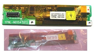
Step 2 - Find replacement part on E-Bay and figure out if the laptop is worth repairing. This is the part, and it cost $20 bucks with expedited shipping. The one I found was used, but hey, its a used laptop.

Here is what was advertised and what was received. Not bad!

Dell Latitude D800 LCD Inverter LP154W01-B3 YPNL-N015A

Step 3 - Prepare the work area! I used a bathroom towel to help prevent parts from getting lost. This technique IS NOT good ESD practice, but this is not an expensive part and there are a bunch of small screws that have to be managed.

Step 4 - Follow the Dell Latitude service manual exactly as it states to prepare the laptop for display removal. But there were some specific experiences that I had that are important to point out.

a) I was hoping to keep the laptop plugged in as a ground, but the manual recommended against it. So instead, I just used my Bass (which delivers excellent static shocks) as a grounded metal surface to frequently touch before manipulating the laptop.

b) The service manual suggested removing the HDD, Memory and other expansion devices. This was not necessary to remove the display, therefore I left those parts alone.

c) Don't forget to remove the battery - the manual states clearly that in no way should the laptop be powered.

d) The manual suggests having a plastic scribe to work parts apart, etc... I found a big nylon tie to be effective and rigid enough. Definitely don't use a screwdriver to pry plastic - the Latitude's plastic is super easy to scratch and break (as you will see below)

Step 5 - Laptop prepared, now after the Display Inverter!

The service manual will have a section on how to remove the display. Follow it. You must first remove the two screws that hold the display in place.

The first thing I encountered was having to remove the main control panel cover. This thing is super flimsy and clearly is easy to break as it is being worked off the main part of the laptop. In particular, the area where the control panel meets the LEDs for power, disk and charging appears very easy to break. Be careful.

On the left side is a recessed notch that can be used by the plastic scribe to pop it out.

The service manual suggests putting the display back 180 degrees - this is actually necessary as the control panel cover cannot be removed safely with the display in the upright position.


Note the circled areas - good tab points to work.

When the control panel cover comes off, don't pull it away. It is connected by a ribbon cable on the far right.


Finally, observe the EMI clip and how the display cable runs under it. You probably want to place it back in its proper position when reassembling. Note in the picture that the display cable has been disconnected.


Step 6 - Free the display from the laptop

Again, following the service manual instructions, you will be lifting the display off the laptop chassis now that the control panel cover has been removed.

In doing this, I carefully lifted it away. The trick here is to not have the display hinges catch the control panel cover which is still wired to the laptop. Two people would work best.


Step 7 - Disassembling the display

This is where things got ugly. First off, the service manual isn't clear about which bumpers to remove. Don't remove the oval bumpers on the sides of the display - there is no screw behind them.


Here is how you can use a nylon cable tie to pop out the bumpers while not marring the plastic surface.


When following the service manual on removing the screws to release the bezel, take note that the two center lower screws are different from the other six 2.5x6mm screws.


With all of the screws removed from the display assembly, the major task is at hand: remove the bezel. This is the most difficult aspect of the repair.

Carefully read the service manual on recommendations from removing the bezel off the display and laptop cover (made of metal).

The bezel is extremely flimsy and can break!


Here is why I broke it - I didn't know which way to work the bezel and lifted up too strongly. What is going on is that the display and laptop cover have hooks that point inward. Consequently, applying force against the outer bezel edge inward toward the display is best to work the bezel off.


Here is a detail on the hooks. This picture shows the bezel on the left which is the part that is to come away from the display and laptop cover.


Here is a detail on the hook that is attached to the display and laptop cover. Note that although it appears that the hook will release the bezel if an upward force is applied to the bezel, this is untrue. If the bezel is pried away from the display and laptop cover, the bezel loops that these hooks catch will break.


Push the bezel edge inward, and use the plastic scribe to apply a gentle upward force.

The bezel really isn't designed to be removed.

Finally, the laptop cover hook that is attached to the display is attached to the display and laptop cover. The hook is NOT attached to the bezel, it is of no use in removing the bezel other than to stabilize the display and laptop cover as the bezel is removed.

Here are the latches on the display case where the bezel really needs to be worked.


The last part of this step is to realize that there are three screws on the right hand side that should not be removed. Here they are two of them. The screws that should be removed are tiny and are in the plane of the LCD.


Step 8 - Smooth sailing from here on out!

You are replacing the display inverter, and the connectors, remaining screw and component replacement is obvious and the service manual effectively describes what needs to be done.

But at this point, there were serious issues with my display!

First, it appears as if a ground was not properly attached to the laptop cover. Can't be too careful with these things especially in noisy electronic environments. Perhaps when the display was in for the vertical line problem this connection was detached? Doubt it, it would have just been cut.


Second, wires were pinched and wire exposed! No wonder this thing failed. Leaking current, no ground, wtf.


Here are the repairs made after the inverter was replaced.

Fixed ground wire.


Repaired and routed the wires.


Step 9 - reassemble and enjoy!

Saturday, November 24, 2007

DIY Wort Chiller

In search of ever faster cold breaks, my wife and I thought a wort chiller would help. One trip to Home Depot and four hours later, here is the result.


What you are looking at is a chiller that is set up to use a water pump to circulate the coolant. Our idea is to circulate ice water through the chiller to increase its cooling capability.
The parts:

The water pump is in the middle, and is being re-used from a fish tank. This is of course a great opportunity for contamination.


$26.53 20' 3/8" OD .0038" wall Copper tubing (Refrigerator grade)
$19.20 15' 8 gauge copper wire (wrong item - use > 8 gauge)
$04.44 10' Vinyl tubing 3/8" OD 1/4" ID
$04.40 3/8"x1/4" Compression coupler for attaching female thread to copper tube
$04.24 3/8" Male threaded 1/4" tube barb
$02.74 1/2" Male threaded 1/4" tube barb for water pump
$04.37 Reduction coupler for water pump

Amortizable/Borrowable items

$08.49 Tube bending tool (set of bending springs)

So for about $70 exclusive the water pump I got to waste an afternoon when I could have easily purchased a chiller for about the same!

Never mind the instructions, if you are intrepid enough to try putting one together, you are going to be able to figure it out. But here are the lessons learned:

- Never build your own wort chiller. Or, only build one for fun. It seems that it is hard to justify the cost and time.

- 8 Gauge copper wire is too difficult to work by hand. Get thinner wire. I suspended the loops of copper tubing by weaving the copper wire between the tubes, with two wraps per tube. I wound up (no pun intended) finding thinner copper wire around the house. Note the use of a spacer.


- Identify an object to use as a mold for this chiller tubing. Here, a 5 gallon PVC bucket perfectly fits in a small boil pot.

- The finalized wort chiller.

Additional points:
  • Clean the oil and dirt off the copper by using white vinegar.

  • When the copper wire is purchased, do not allow the store to tape or label the wire - the adhesive backing is difficult to remove from the wire.

  • Plan carefully the inlet and outlet - I sized the chiller against several different pots.

  • Consider drip loops for the inlet and outlet - in the picture above, they appear at a ninety degree angle, but condensate and leaks are going to clearly slide down the neck into the wort. Consider pointing the inlet and outlet downwards.

Results from having used the chiller:

  • First off, the boil is HOT. If you DIY a chiller, consider that heat conducts and the entire apparatus will come up to temperature. In our first usage, we threw the chiller in during the boil to sanitize it. The result is that the vinyl intake/outake tubes practically melted. Next time, we will first sanitize the chill with iodophor and remove the heat before immersion.

  • When the chiller was placed into the boil, it immediately refluxed. This is an important point to your DIY design - the air and remainder water from testing remains inside the chiller. When immersed, the air rapidly expands and remaining water gurgles out the intake and outake. Of course if you are connecting it to mains, this is less a problem. We are using a water pump which had to fight head pressure from the expansion of air.

  • Though the vinyl is tough, it will chemically alter from the heat and our chiller's vinyl tubing near the copper now has a pretty good haze.

  • The vinyl tubing is connected to barbs. When heated from immersion in the boil, the barbs were no longer effective in anchoring the vinyl tubing and minor leakage occured.

  • Apparently compression fittings need LOTS of compression - ours leaked slightly risking wort contamination.

  • Thought I planned carefully the inlet and outlet, you cannot leave too much - the heat conducts across copper like crazy. Leave at least a foot!

  • The next time we use this chiller, it is going to work really well. Maybe the beer master will post the temperature curve for us...


- Detail on the vinyl tubing - note the steam refluxing into the lower tube. Keep the flow going on immersion! The vinyl became quite soft and there was concern it would fall off the barbs.

- the whole setup in action! The main lesson is to bring the temperature down with mains water from 120 to about 90 and then to throw ice in and bring it down from 90 to the objective temperature. We had lots of ice, and it melted quite quickly!

Saturday, April 21, 2007

Importing and Exporting Contacts from Outlook using Excel

MS Excel 2002 10.6501.6735 SP3
MS Outlook 2002 10.6515.6735 SP3

If you try and use the import/export feature of Outlook to manage contacts, good luck. Outlook is heavily design biased to be the primary manager of the contacts. It doesn't like to export its contacts, have them manipulate and the imported back in. If you manually export your contacts think of it as a one way operation. And importing contacts gets a little more challenging.

There are great third party applications (e.g. Intellsync in the ubiquitous Blackberry Desktop Manager) but you think you can outsmart things and use MS Excel to quickly manage and manipulate your contacts outside of Outlook. Maybe you have no reason, but here is the trick to round trip edit your contacts using MS Excel: Named Ranges.

The best way to get a template XLS file is to first export the MS Outlook contacts. I'm sure you can figure out how to do this. If not, you probably wouldn't want to anyway.

Take a look at the exported file: It will have the columns that you want, and the data that is expected. But it is easy to miss the 'Named Range' that was created in the Excel XLS file. You can't simply manipulate your contact data without understanding that the Named Range must be managed too.

Named Ranges are managed by the menu options Insert->Name->Define. Once you see the Define Name window things get obvious. You will see that MS Outlook created a Named Range called 'Contacts'. In the Refers To field at the bottom of the Define Name window, you will be able to click on the 'show me the range' icon in the bottom right and see the extent of the Named Range.

There is also another trick to know what is in the Excel document. Take a look at the menu File->Properties and select the Contents tab. This is an excellent way to get the gist of what is in the XLS file.

Edit away on your contacts! But then update the Named Range. "=Contacts!$A$1:$CN$178" may be the Named Range exported, so make sure to edit the Named Range to reflect added rows. How do you add a new or update your Named Range? If you read this far, it will be a no brainer to figure out.

When you wish to Import back into MS Outlook your contacts, be sure to define or update your Named Range. And good luck with the two or three other issues you will hit - e.g. be sure to put a tick (') in front of all your entered fields in the XLS file!

Named Range. Get it?

Wednesday, March 14, 2007

How to open the Western Digital My Book 500GB

Do not be stupid and leave the unit plugged in or plug it in during disassembly. And you are about to void any warranty you may have.

Model: WD5000C032

Step one

Identify the corner screw that is painted black. It is located by the lock hole. Scrape it clean and unscrew it. The two clam shells that form the My Book are very snug.


Step two

Put the My Book up on its end, the long rubber feet down. Locate the locking tab (See step four). It will be visible through the grille. Push locking tab down with screw driver (pink) and insert another (red) to torque the two clam shells apart. Be gentle, the plastic is soft and chances are it will get marred. Torque the clam shells apart just enough to prevent the tab from locking.
Step Three

Flip it over and do the same. But just enough to get the locking tab to not lock. Flip it over, and continue to repeat steps two and three until you can pry the clam shells apart with your fingers or a soft instrument.

Step Four

Note the locking tabs; it will help you visualize what is to be done in steps two and three. Step the outer clamshell aside and lay the hard drive caddy flat. Observe the white transparent LED button that is used to power the My Book on and off.

Step Five

Do not attempt to remove the hard drive. There is much work yet to be done. Notice how the drive screws are inaccessible.

Step Six

Unscrew the three screws that hold the LED PCB in place.


Step Seven

Remove the LED PCB. It is connected by pins, so wiggle it gently until it disconnects.


Step Eight

Now this is the second hard part. The first was opening the clamshell I’m sure you will agree. The power supply PCB on the bottom of the drive caddy must be loosened so that the LED PCB connector can clear the plastic clamshell. Loosen the two screws nearest the LED connector. You may have to remove some aluminum tape that holds the HDD connectors in place.
Step Nine

It can’t be explained. Just keep manipulating the HDD caddy until it comes out of the plastic clamshell.
Step Ten

Now remove the other two screws from the power supply cage. This is necessary so that the HDD screws can be removed without damaging the sheet metal that forms the power connector housing.

Step Ten

Now remove the other two screws from the power supply cage. This is necessary so that the HDD screws can be removed without damaging the sheet metal that forms the power connector housing.

Step Twelve

You should screw the power supply cage back on at this point: the posts that are inside it are going to float around and impact components and traces as the other three HDD screws are removed.

Step Thirteen

Remove the HDD cables.

Step Fourteen

The HDD may be removed by wiggling it free of the rubber shock mounts to which it is attached.

Congratulations. Enjoy replacing the drive.


Sunday, February 4, 2007

Lexmark E352dn - an excellent network printer

After owning a Samsung SCX-4X16 series printer and HP Officejet Model 710, it was becoming clear that consumer multifunction printers are very poor products in general. Too complex, too much host side software needed and poor vendor support. Over time, the Samsung developed both parallel and USB connectivity problems (tried to correct through three different hosts, different cables, same behavior resulted). The HP just couldn't function until its host side software worked which it rarely did. The best malfunction of this printer was printing one letter of a document on a scale that spread it across four pages.

These two experiences showed a couple things:

  • Multifunctional printers do not do one thing well but may do many things poorly.
  • If host side software is required, the printer will eventually be unusable as the OS marches forward in its patching.
  • Devices that require a host to be turned on to be network shared are just about useless in this day and age of home wireless networks.

Recommendations buying a new printer:

  • Don't go multifunctional.
  • Make sure it is network based and does not have to be connected to a PC
  • Make sure it can support more than just MS Windows (this forces a much better designed device)
After searching for a new printer the Lexmark E352dn came up as a pretty good bet - and it has been absolutely perfect so far.

Unpacked the new E352dn
Plugged in the printer to my wireless router via ethernet so that it could be accessed from all my 802.11 hosts in the house.

Here is what was observed:
  • Is a DHCP client
  • Has a web server http://192.168.1.103/
  • Does not share any filesystem \\192.168.1.103
  • Has an FTP Server (for what purpose?)
$ ftp 192.168.1.103
Connected to 192.168.1.103.
220 ET000400C5F980 Lexmark E352dn FTP Server NZ0.NA.N001 ready.
User (192.168.1.103:(none)):
230 User default logged in.
ftp> dir
200 PORT command successful.
150 Opening ASCII data connection (192.168.1.101,5001).
Total 0
226 Transfer complete.
ftp: 9 bytes received in 0.00Seconds 9000.00Kbytes/sec.
ftp> pwd
257 "/prt0" is the current directory.
ftp>

Install Experience
But I didn't get far with my, "Never install the CD that comes with the product". The printer drivers were needed in order to add a network printer to Windows. Of course that is easily done after unpacking and connecting the Lexmark - another indicator of excellent product quality.

Using MS Windows, specifically search for the drivers off the CD that comes with the E352dn. Don't use its setup.exe or autorun features. Once the drivers are installed, the printer will work like a charm. Interestingly enough, directly installing the drivers circumvents the affirmative assent license agreement that is supposed to be accepted.


Driver install details:

  • Installed E352dn driver (PCL?)
  • Installed E352dn PS3 driver
  • This installs two different printers.


Went back to web interface and noticed a static IP Address could be set up

http://192.168.1.103/
Gave it a reasonable hostname, "Lexmark E352dn"
Printer Server Settings->TCP/IP->Set static IP address
Once this address is changed, you have to update the driver port settings. Right click on the Lexmark in the "Printers & Faxes" control panel, choose properties->Ports tab and re-configure the previously set up ports.


Examined CD for extras

Ran setup.exe and chose custom option->Select components->Local (using previously configured local printers)

Components (IP Setup Utility AFAIK) can be installed in different locations but the browse folder functionality is unusable. The default drive, C, can't be changed without have to manually retype default path.


Driver Profiler

  • Sets profile defaults for the driver when the drivers are installed by script. I think these are the 'Printers & Faxes'->Right click on Lexmark printer->Printer Preferences (Also available on Print panel from application's print menu option)
  • So I skipped it.

Enhanced Communication Software & Status Window

Tools - IP Setup Utility & Screen Fonts
  • Skipped IP Setup Utility - seems like all the TCP/IP configs can be done through the web interface


Alas, stuff is installed that we were not expecting: C:\Program Files\Lexmark_HostCD\Install\ some doc installs here as well as the installer. Guess it has to go somewhere.

Uninstaller

Uninstalls really cleanly and also recognizes printers installed using Windows Printer and Faxes control panel so those can be uninstalled if manually setup as described above.


Host Software Summary

Excellent software, open minded approach to configuration, "If you installed your printer driver without using the Software and Documentation CD, you can still install your screen fonts from the [install cd]".

Annoyances
  • Setup.exe installer makes it hard to change the install path of components
  • The properties panel is slow to show when printing from within applications: File->Print->Properties takes too long to display (probably talks across my wireless network)
  • The
  • When the printer properties "2 Sided Printing" is set to "Use printer settings" a "Manual Duplex" checkbox shows up on the print panel. This is the off the shelf configuration and is surprising to see since the printer comes with an automatic, not manual duplexer. Of course this is due to Windows allowing us to manually duplex be re-feeding a document. So it is a feature, not a bug. (Seriously, the automatic duplex does long edge and short edge duplex printing but manual duplex allows various rotations if needed)
  • The included doc didn't seem to say anything about the duplexing feature
  • The duplexer is not internal... rather a sheet is ejected and then pulled back off the output tray - a little suprising if you are watching the printer.
Quick Setup

Here is a picture journal of the driver install. This is the bare minimum required.


Yeah, counterintuitive: a local printer has to be configured. I'm unsure why the E352dn cannot be directly treated as a network printer.